Parts of the Controller
WR‑R11a
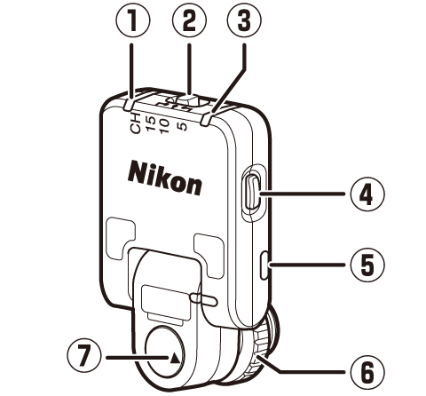
| 1 |
Red LED |
|---|---|
| 2 |
Channel selector |
| 3 |
Green LED |
| 4 |
Pairing button |
| 5 |
Strap eyelet |
|---|---|
| 6 |
Locking screw |
| 7 |
Mounting mark (d) |
WR‑R11b
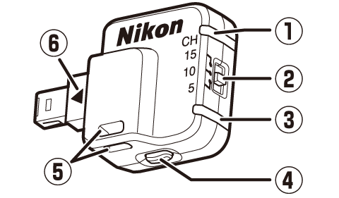
| 1 |
Red LED |
|---|---|
| 2 |
Channel selector |
| 3 |
Green LED |
| 4 |
Pairing button |
|---|---|
| 5 |
Strap eyelet |
| 6 |
Mounting mark (d) |
WR-T10
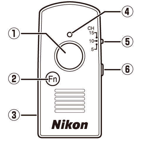
| 1 |
Shutter-release button |
|---|---|
| 2 |
Fn button |
| 3 |
Strap eyelet |
| 4 |
Red LED |
|---|---|
| 5 |
Channel selector |
| 6 |
Pairing button |
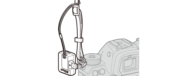
Attach the controller to the camera strap as shown to prevent it being lost or dropped.
The function performed by pressing the Fn button on the WR‑T10 is assigned by the camera. Its role varies depending on the camera to which the WR‑R11a/WR‑R11b is attached.
-
In the case of cameras with menu items controlling the behavior of Fn buttons on remote controllers ([], [], [], or []), it performs the role assigned in the menus. The name of the relevant menu item and its location vary with the camera.
-
If you are using a D4, D800, or D800E, be sure the camera firmware is up-to-date.
-
-
In the case of the D7100, D5300, and D5200, it performs the same role as the camera Fn button.
-
With all other cameras, it activates the standby timer.
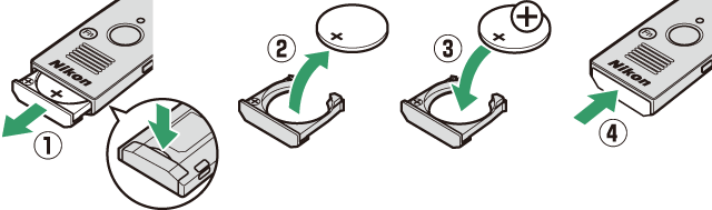
Replace the battery when the LED for the WR‑T10 starts to dim. Insert a fingernail behind the battery-chamber latch and open the battery chamber (q). Ensure that the battery is inserted in the correct orientation (e).